Project Critter is a long-duration CubeSat mission focused on autonomous operation,
resilient communications, and modular in-orbit software systems.
The mission is designed for survivability, remote maintainability, and controlled extensibility
over a planned operational lifespan of 2–5 years in low Earth orbit (LEO).
[DISCLAIMER]
This summary describes intent and architectural direction only.
Specific behaviors, interactions, and operational modes are governed by software policy, regulatory constraints,
and mission rules that will be defined and validated separately.
END OF LINE...
Mission Philosophy
Project Critter prioritizes autonomy, recoverability, and long-term survivability. The spacecraft is designed to continue operating under degraded conditions and favors software-driven solutions wherever possible.
Mission Objectives
Primary Objectives
- Achieve stable insertion into low Earth orbit
- Maintain autonomous operation for a minimum of two years
- Sustain onboard power, communications, and thermal stability
- Enable remote system updates and maintenance
- Demonstrate modular and fault-tolerant flight software
Secondary Objectives
- Capture physical observation and imaging data
- Conduct signal and network reconnaissance experiments
- Collect long-term telemetry and performance metrics
- Validate recovery from partial system failures
Spacecraft Configuration
Platform
- CubeSat-class spacecraft (final U-size TBD)
- Modular internal subsystem layout with electrically isolated domains
- Thermal dissipation and radiation tolerance prioritized
Onboard Flight Systems Controller
- Primary onboard computing and control system responsible for mission-wide coordination
- Based on one or more Raspberry Pi units (Raspberry Pi 3B+ minimum, scalable up to Raspberry Pi 5)
- Executes all flight software including communications, power management, telemetry, imaging, and system health monitoring
- Manages command reception, validation, scheduling, and execution
- Controls subsystem power states, watchdogs, and recovery procedures
- Maintains onboard timekeeping, logging, and persistent mission state
- Interfaces with sensors, radios, storage, and payload systems via GPIO, UART, I²C, SPI, and USB as required
Redundancy & Fault Tolerance
- Preferred dual-controller configuration with a primary and secondary Raspberry Pi
- Secondary unit functions as a cold or warm standby backup capable of assuming control
- Optional use of the secondary unit as an emergency data vault or system image clone
- Independent power gating to allow hard resets and isolation of failed units
- Software-controlled heartbeat monitoring between controllers
- Automatic failover or ground-commanded role reassignment
Power System
- Solar-based primary power generation
- Onboard energy storage with conditioning and protection
- Software-controlled power distribution to all subsystems
- Priority-based load shedding under low-power conditions
Communications Architecture
Uplink & Control
- Secure command and control uplink
- SSH-based remote interaction framework
- Encrypted command execution and data transfer
Redundancy & Recovery
- Failsafe communication modes
- Watchdog-driven recovery logic
- Autonomous reboot and reconnect sequences
Flight Software Architecture
Core Systems
- BlackBird II — Secure communications, updating, orchestration
- HotBox — System health and environmental monitoring
- SysBot — Automated reporting and status aggregation
- CamGo — Imaging and physical observation
Advanced Mission Software
Internally referred to as the Project Package.
- AirKommander II — Wireless and signal experimentation
- Holocron — ASN and IP range intelligence database
- QMap — Network scanning and mapping
- ReconX — Domain reconnaissance and intelligence
- Kasha — Information gathering and data mining
- Kytn — Information gathering and data mining
Data Handling & Storage
- Onboard storage for telemetry and mission data
- Priority-based retention policies
- Scheduled downlink of critical datasets
- Graceful degradation under storage constraints
Fault Tolerance & Reliability
- Isolated failure domains
- Process watchdogs
- Automated restart and fallback logic
- Post-event logging and forensic retention
Risk Considerations
- Radiation-induced faults
- Power degradation over mission lifetime
- Intermittent communications windows
- Limited post-deployment recovery options
Preliminary Power Consumption Estimates
The following power consumption figures represent preliminary, ballpark estimates based on currently anticipated onboard hardware. Final values will be refined once the complete hardware configuration and duty cycles are defined.
Primary Compute & Storage
- Onboard Flight Systems Controller (Raspberry Pi)
- Raspberry Pi 3B+ (idle to moderate load): ~2.0–4.0 W
- Raspberry Pi 4 / 5 (idle to moderate load): ~3.0–6.5 W
- Peak consumption during high CPU or I/O activity may exceed averages
- Solid-State Storage (USB or NVMe via adapter)
- Per SSD (idle to active): ~1.0–3.0 W
- Dual-drive configuration: ~2.0–6.0 W total
- Higher draw expected during sustained writes or imaging operations
Imaging & Payload Devices
- Camera Module (CamGo payload)
- Idle or standby: <0.5 W
- Active capture or video: ~1.0–2.5 W
- Burst activity expected during scheduled observation windows
Peripheral & GPIO Devices
- Low-power sensors (temperature, voltage, current): <0.2 W combined
- GPIO-controlled devices and indicators: <0.5 W (typical)
- Serial, I²C, and SPI peripherals expected to contribute minimally to overall draw
Aggregate System Estimate
- Low-activity baseline: ~5–8 W
- Nominal operational load: ~8–14 W
- Peak activity (imaging + I/O): ~14–20+ W
Power Management Considerations
- Dynamic power scaling based on mission phase and subsystem demand
- Ability to power-gate non-essential devices
- Staggered activation of high-draw components
- Fallback low-power operational modes during power-constrained periods
These estimates are intentionally conservative and subject to change. Actual consumption will depend on processor selection, clocking, peripheral usage, storage technology, environmental conditions, and software behavior.
Preliminary Power Generation (Hybrid Solar + Thermoelectric)
Project Critter is planned around a hybrid electrical power system where photovoltaic (PV) solar arrays provide primary generation, and thermoelectric generation (TEG) is evaluated as a supplemental source for opportunistic recovery of waste heat. Final sizing will be refined once the full power budget, duty cycles, orbit, and thermal design are locked.
Primary Generation: Space-Rated Solar (PV)
- Baseline approach: body-mounted and/or deployable solar arrays feeding an EPS with MPPT (Maximum Power Point Tracking)
- Cell technology (current standard): multi-junction GaAs / III-V space cells are common in CubeSat-class missions and can reach ~29–30% class efficiency in space-rated implementations :contentReference[oaicite:1]{index=1}
- Power density (ballpark): vendors often publish AM0/LEO generation on the order of tens of mW/cm² (example: ~36.85 mW/cm² quoted for a CubeSat GaAs panel design) :contentReference[oaicite:2]{index=2}
- Key constraint: available surface area and sun-pointing geometry dominate actual delivered power (generation is not constant and drops during eclipse)
- Degradation: expected performance reduction over mission life due to radiation and thermal cycling
Next-Gen Solar Options (Evaluation Track)
- Perovskite tandems: record laboratory tandem efficiencies are now well above traditional single-junction silicon (recent validated records in the mid-30% range are reported), but long-term space durability and flight heritage are still an active area :contentReference[oaicite:3]{index=3}
- Plan: treat perovskite/tandem PV as an R&D candidate unless flight-proven modules are available for the intended environment
Supplemental Generation: Thermoelectric (TEG)
- Purpose: recover small amounts of electrical power from temperature gradients across spacecraft hot and cold regions (waste heat harvesting)
- Reality check: typical commercially available thermoelectric devices are often in the ~5–6% efficiency class, and performance depends heavily on maintaining a strong temperature difference :contentReference[oaicite:4]{index=4}
- Best-use cases for CubeSats:
- Across a controlled hot-side source (processor / power regulators / RF amplifier area) to a radiator-coupled cold side
- As a trickle contributor during specific thermal conditions rather than a primary power source
- As an experimental subsystem for long-duration thermal telemetry and efficiency characterization
- Design caution: TEGs add thermal coupling requirements; the spacecraft thermal design must remain stable first, and TEG integration must not create hot spots or reduce radiator effectiveness
Hybrid EPS Architecture
- Solar PV → MPPT channels → regulated power bus
- Battery storage → eclipse operations + peak load buffering
- TEG module(s) → dedicated boost/charge path (optional) → auxiliary bus or battery trickle
- Power gating for high-draw loads (compute, storage, imaging) with priority-based load shedding
Preliminary Sizing Notes (Non-Final)
- Daylight generation must cover instantaneous loads plus battery recharge margin for eclipse periods
- Eclipse operations should target a reduced power profile (low-power mode) whenever possible
- TEG contribution should be modeled as “bonus power” unless a verified thermal gradient and conversion path are demonstrated in testing
This section is intentionally preliminary. Final solar area, battery capacity, MPPT topology, and TEG feasibility will be refined after the full load list and duty cycle schedule are established.
Preliminary Power Generation (Example Data)
This section provides example-only generation numbers to illustrate how a hybrid power system can be budgeted and reasoned about. These figures are not final and will be recalculated once solar area, pointing strategy, EPS topology (MPPT count), orbit details, and the complete load list are defined.
Solar PV (Primary Generation)
- Assumption: space-grade multi-junction PV is the primary source (typical ~29–31% class BOL for space-qualified triple-junction cells) :contentReference[oaicite:1]{index=1}
- Example vendor reference: CubeSat GaAs panel listings show on the order of ~36.85 mW/cm² (example spec) and other panels list ~43.24 mW/cm² “generation capacity in LEO” (example spec) :contentReference[oaicite:2]{index=2}
- Reality: delivered power depends heavily on illumination, attitude, temperature, degradation, and eclipse time
Thermoelectric (TEG) Supplemental Generation
- Assumption: TEG is supplemental only and treated as “bonus power” unless test data proves a stable temperature gradient
- Rule of thumb: low-temperature TEG theoretical efficiency is only around ~5–8% class and depends strongly on ΔT :contentReference[oaicite:3]{index=3}
- Typical CubeSat use case: waste-heat recovery across a controlled hot zone (compute/EPS) to a radiator-coupled cold zone
Example Data Table (Not Final)
Example generation ranges below assume “effective illuminated PV area” and common space PV behavior. Replace these values once your actual panel area, layout, and attitude profile are known.
Example Inputs (Illustrative)
- PV Tech: Space-rated triple-junction class (BOL ~29–31% typical)
- Effective illuminated PV area: 100–250 cm² (example only)
- PV power density reference points: ~37–43 mW/cm² (example vendor specs)
- TEG: Supplemental waste-heat recovery only; depends on ΔT and thermal design

Example Power Generation Ranges
+-----------------------------+------------------------+----------------------------+
| Source                      | Example Condition      | Example Output (Watts)     |
+-----------------------------+------------------------+----------------------------+
| Solar PV                    | 100 cm² effective      | ~3.7 to 4.3 W              |
| Solar PV                    | 150 cm² effective      | ~5.6 to 6.5 W              |
| Solar PV                    | 250 cm² effective      | ~9.2 to 10.8 W             |
| TEG (supplemental)          | modest ΔT              | ~0.05 to 0.30 W            |
| TEG (supplemental)          | strong ΔT (best case)  | ~0.30 to 1.00 W (rare)     |
+-----------------------------+------------------------+----------------------------+

Notes
- “Effective illuminated area” is not the same as total panel area.
- Actual PV output varies with pointing, temperature, eclipse, and degradation.
- TEG numbers are highly dependent on thermal gradient and heatsinking.
Hybrid EPS Strategy (Design Intent)
- Solar PV feeds MPPT channel(s) into the regulated bus and battery charge path
- Battery provides eclipse operations and peak-load buffering
- TEG (if implemented) feeds a dedicated low-power boost path for trickle contribution or auxiliary bus support
- Load shedding and power gating used to protect battery SOC during constrained periods
Example Data Only: This table is a planning tool to help frame system sizing. Final generation numbers will be generated from the actual solar array geometry, orbit lighting model, EPS efficiency, and mission duty cycles.
Daylight vs Eclipse Energy Budget (Example Data)
This section illustrates how to account for energy across an orbit using watt-hours (Wh). Values below are example-only placeholders to help shape sizing logic for solar area, battery capacity, and safe-mode planning.
Example Assumptions (Illustrative)
- Orbit period: 90 minutes (example)
- Sunlight time: 60 minutes (example)
- Eclipse time: 30 minutes (example)
- EPS efficiency (PV to bus/battery): 0.85 (example)
- Battery round-trip efficiency: 0.90 (example)
Example Power Levels (Illustrative)
- Average PV generation during sunlight: 8 W (example)
- Average bus load during sunlight (nominal ops): 10 W (example)
- Average bus load during eclipse (reduced mode): 6 W (example)
Per-Orbit Accounting (Wh/orbit)
Formulas
- Energy (Wh) = Power (W) × Time (hours)
- PV delivered to bus/battery = PV_W × Sunlight_hr × EPS_eff

Example Times
- Sunlight_hr = 60 min / 60 = 1.00 hr
- Eclipse_hr  = 30 min / 60 = 0.50 hr

Generation (Sunlight)
- PV_delivered = 8 W × 1.00 hr × 0.85 = 6.80 Wh

Consumption
- Day_load     = 10 W × 1.00 hr = 10.00 Wh
- Eclipse_load =  6 W × 0.50 hr =  3.00 Wh
- Total_load   = 13.00 Wh

Net Energy (per orbit)
- Net = PV_delivered - Total_load
- Net = 6.80 Wh - 13.00 Wh = -6.20 Wh (battery must cover deficit)

Battery Impact (very simplified)
- Battery_drawn ≈ 6.20 Wh / Battery_eff (0.90) = 6.89 Wh per orbit
What This Example Demonstrates
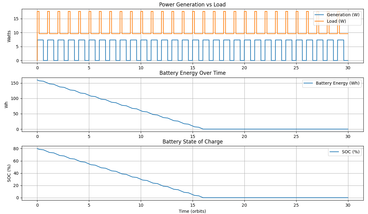
- If PV delivered energy is less than total load energy, the battery state-of-charge will decrease each orbit
- To stabilize long-duration operation, one or more of the following must improve:
- Increase effective PV area and/or pointing efficiency
- Reduce nominal daytime load (or shorten high-draw duty cycles)
- Reduce eclipse load via strict low-power mode
- Increase EPS efficiency and reduce conversion losses
- TEG (if used) should be treated as small supplemental energy unless validated by testing
Safe-Mode Example (Illustrative)
One common strategy is to enforce an eclipse safe-mode profile and only enable high-draw operations (imaging, heavy storage writes, long TX bursts) during sunlight when the power budget is positive.
Example Safe-Mode Targets (Not Final)
- Eclipse load goal: 3–5 W
- Daytime nominal goal: 6–10 W
- “Burst” loads allowed only when battery SOC is above threshold
Example Data Only: Replace sunlight/eclipses, PV power, EPS efficiency, and load profiles once orbit parameters, pointing strategy, and the full subsystem list are finalized.
Battery State-of-Charge (SOC) Policy (Example Data)
This section defines an example-only battery State-of-Charge (SOC) policy used to gate subsystem activity and protect long-term mission survivability. Thresholds and behaviors are illustrative and will be refined once battery chemistry, capacity, and degradation models are finalized.
Design Intent
- Prevent deep discharge and extend battery service life
- Prioritize command, telemetry, and recovery capability at all times
- Allow higher-risk or high-draw operations only when sufficient energy margin exists
- Ensure deterministic behavior under low-power conditions
Example SOC Thresholds & Behavior
+----------------+-------------------------------+------------------------------------+
| SOC Range      | System Mode                   | Allowed Operations                 |
+----------------+-------------------------------+------------------------------------+
| 80–100%        | Nominal / Full Operations     | All systems enabled                |
|                |                               | Imaging, storage writes, TX bursts |
+----------------+-------------------------------+------------------------------------+
| 60–80%         | Nominal (Conservative)        | Comms, telemetry, compute          |
|                |                               | Imaging limited or scheduled       |
+----------------+-------------------------------+------------------------------------+
| 40–60%         | Reduced Power Mode            | Essential compute                  |
|                |                               | Telemetry, short TX windows        |
+----------------+-------------------------------+------------------------------------+
| 25–40%         | Safe Mode                     | Command receive                    |
|                |                               | Minimal telemetry                  |
|                |                               | Payloads disabled                  |
+----------------+-------------------------------+------------------------------------+
| < 25%          | Emergency / Survival Mode     | EPS + flight controller only       |
|                |                               | Periodic beacon if possible        |
+----------------+-------------------------------+------------------------------------+
Control & Enforcement
- SOC evaluated continuously by the onboard flight systems controller
- Threshold crossings trigger deterministic mode transitions
- Subsystems are power-gated or throttled automatically based on active mode
- Manual ground override permitted only above defined SOC safety floor
Recovery Strategy
- Exit from Safe or Emergency modes requires sustained positive energy balance
- Payloads remain locked out until SOC stabilizes above recovery threshold
- Hysteresis applied to prevent rapid mode flapping
Example Data Only: SOC thresholds, allowed operations, and recovery rules will be tuned based on battery chemistry, thermal behavior, aging, and in-orbit performance data.
EPS Control Authority & Arbitration (Example Data)
This section defines control authority over electrical power distribution and the arbitration rules that govern which subsystem may enable, disable, or override power states. The intent is to ensure deterministic behavior under both nominal and fault conditions.
Authority Hierarchy
- Electrical Power System (EPS) — ultimate authority over power distribution
- Primary Flight Systems Controller — operational control within EPS-defined limits
- Secondary / Backup Controller — limited authority, recovery-focused
- Payloads & Peripherals — no direct power authority
Power Control Capabilities
- EPS may unconditionally remove power from any non-critical subsystem
- EPS may remove power from the primary controller only if the backup controller is powered
- Flight controller may request power state changes but cannot override EPS hard limits
- Payloads may request activation but cannot self-enable power
Arbitration Rules
- EPS safety rules always override software requests
- SOC, battery voltage, and thermal limits are enforced at the EPS level
- Conflicting requests are resolved in favor of system survivability
- Ground commands cannot bypass EPS hard safety floors
Example Data Only: Final authority boundaries will depend on EPS hardware capabilities and controller-to-EPS interface design.
Boot Order vs State-of-Charge (SOC) (Example Data)
This section defines which subsystems are permitted to boot or remain active based on available battery State-of-Charge. Boot sequencing is used to prevent brownouts and cascading failures during low-energy conditions.
Boot Priority Order
- EPS core logic and protection circuits
- Primary flight systems controller
- Secondary / backup controller (if enabled)
- Communications subsystem
- Telemetry and health monitoring
- Storage devices
- Payloads and experimental subsystems
Example SOC-Based Boot Permissions
+----------------+---------------------------------------------+
| SOC Range      | Allowed Boot / Active Subsystems            |
+----------------+---------------------------------------------+
| 80–100%        | All systems and payloads                    |
| 60–80%         | Controllers, comms, storage, limited payload|
| 40–60%         | Primary controller, comms, telemetry        |
| 25–40%         | Primary controller + EPS only               |
| < 25%          | EPS core + minimal controller logic         |
+----------------+---------------------------------------------+
Boot Enforcement
- Subsystems not permitted at current SOC remain power-gated
- Deferred boot attempts are retried only after SOC recovery
- Ground commands cannot force boot below defined SOC floor
Example Data Only: SOC thresholds and boot permissions will be tuned based on battery chemistry, inrush current behavior, and EPS response time.
Power Degradation Policy Over Mission Life (Example Data)
Battery capacity and power generation capability are expected to degrade over the operational lifetime of the spacecraft. This section defines example policies for adapting SOC thresholds and operational behavior as degradation occurs.
Degradation Drivers
- Battery capacity fade due to charge/discharge cycling
- Increased internal resistance over time
- Solar array degradation from radiation and thermal cycling
- Reduced efficiency of power electronics
Adaptive SOC Threshold Strategy
Example Adjustment (Illustrative)
- Beginning of Life (BOL):
  Safe Mode threshold: 40%
  Emergency threshold: 25%

- Mid-Life (estimated 50% capacity loss):
  Safe Mode threshold: 50%
  Emergency threshold: 35%

- Late-Life:
  Safe Mode threshold: 60%
  Emergency threshold: 45%
Operational Implications
- High-draw payload operations become increasingly restricted over time
- Imaging and experimental subsystems may be permanently disabled in late life
- Mission focus shifts toward telemetry, beaconing, and data return
- Power margins preserved to maximize mission longevity
Control & Telemetry
- Degradation trends tracked via long-term telemetry
- Threshold adjustments may be commanded from ground or applied autonomously
- Policy updates logged and versioned onboard
Example Data Only: Actual degradation curves will be determined from in-orbit telemetry and validated against pre-flight testing.
EPS ↔ Flight Controller Interface Signals (Example Data)
This section defines the electrical and logical interface between the Electrical Power System (EPS) and the onboard flight systems controller. Signals described here establish power authority, health reporting, fault response, and controlled startup and shutdown behavior.
Design Intent
- Ensure EPS maintains ultimate authority over power safety
- Provide the flight controller sufficient visibility to make informed decisions
- Enable deterministic recovery from faults and brownout conditions
- Support both autonomous and ground-commanded control paths
Signal Categories
- Power Control Signals — enable, disable, and hard cutoff
- Status & Telemetry Signals — voltage, current, SOC, temperature
- Fault & Protection Signals — brownout, overcurrent, thermal limits
- Heartbeat & Liveness Signals — controller health monitoring
Example Interface Signals
+----------------------+-------------------+-------------------------------+--------------------------+
| Signal Name          | Direction         | Type                          | Purpose                  |
+----------------------+-------------------+-------------------------------+--------------------------+
| MAIN_PWR_EN          | EPS → Controller  | Digital (latched)             | Enables main controller  |
| BACKUP_PWR_EN        | EPS → Controller  | Digital (latched)             | Enables backup controller|
| PAYLOAD_PWR_EN[x]    | EPS → Subsystems  | Digital (switched rails)      | Payload power gating     |
| CONTROLLER_HEARTBEAT | Controller → EPS  | Digital (periodic toggle)     | Liveness indication      |
| EPS_FAULT            | EPS → Controller  | Digital (interrupt)           | Fault notification       |
| EPS_WARN             | EPS → Controller  | Digital (interrupt)           | Approaching limits       |
| BUS_VOLTAGE          | EPS → Controller  | Analog / ADC                  | Main bus voltage         |
| BUS_CURRENT          | EPS → Controller  | Analog / ADC                  | Bus current draw         |
| BATTERY_SOC          | EPS → Controller  | Digital (I²C / SPI / UART)    | State-of-charge          |
| BATTERY_TEMP         | EPS → Controller  | Analog / Digital              | Battery temperature      |
| KILL_LINE            | EPS → All         | Hardware (non-maskable)       | Emergency power cutoff   |
+----------------------+-------------------+-------------------------------+--------------------------+
Heartbeat & Watchdog Behavior
- Primary controller asserts a periodic heartbeat signal to the EPS
- Loss of heartbeat beyond a defined timeout is treated as controller failure
- EPS may power-cycle or disable the controller upon heartbeat loss
- Backup controller may be enabled automatically following a primary failure
Fault Handling & Arbitration
- EPS faults are treated as authoritative and non-ignorable
- Controller must immediately reduce load or enter safe mode upon EPS_FAULT
- Repeated fault events may trigger enforced subsystem lockout
- KILL_LINE bypasses software and removes power regardless of controller state
Communications Interface
- Low-speed digital bus (I²C, SPI, or UART) used for detailed telemetry exchange
- Bus selected for simplicity, robustness, and deterministic timing
- Telemetry includes SOC, voltage, current, temperature, and fault counters
Startup & Shutdown Coordination
- EPS validates voltage and SOC before asserting MAIN_PWR_EN
- Controller signals readiness after boot and stabilization
- Graceful shutdown requests may be issued before hard power removal
- EPS may bypass graceful shutdown during fault conditions
Example Data Only: Actual signal names, voltage levels, bus selection, and timing parameters will be finalized during EPS hardware design and integration testing.
Watchdog & Kill-Line Timing Diagrams (Textual) (Example Data)
This section provides example-only textual timing diagrams describing watchdog behavior and the EPS kill-line response. Timing values are illustrative placeholders until validated through integration testing.
Controller Heartbeat Watchdog (Example)
Signals
- CONTROLLER_HEARTBEAT: controller toggles periodically
- EPS_WDT_TIMER: EPS internal watchdog window
- MAIN_PWR_EN: EPS power-enable to primary controller

Example Timing (illustrative)
t=0s     MAIN_PWR_EN asserted (primary controller powered)
t=0-10s  controller boot + stabilization
t=10s    controller begins toggling CONTROLLER_HEARTBEAT (1 Hz example)
t=10-∞   EPS expects heartbeat transition at least once per 2.5s window

Failure Case (heartbeat loss)
t=120s   heartbeat stops (controller hang or crash)
t=122.5s EPS watchdog window exceeded (no transitions detected)
t=123s   EPS action: power-cycle primary controller (remove MAIN_PWR_EN)
t=123-126s off-time (brownout recovery delay)
t=126s   MAIN_PWR_EN reasserted (reboot primary)
If repeated failures exceed limit → transition to failover sequence.
Kill-Line Event (Example)
Signals
- KILL_LINE: EPS non-maskable emergency cutoff (hardware)
- PAYLOAD_PWR_EN[x]: power rails to non-essential subsystems
- MAIN_PWR_EN / BACKUP_PWR_EN: controller power enables

Trigger Conditions (examples)
- severe undervoltage (bus collapse)
- critical overcurrent
- thermal runaway / battery protection threshold

Example Kill-Line Sequence
t=0ms    EPS detects critical condition
t=1ms    EPS deasserts PAYLOAD_PWR_EN[x] (drop non-essential loads first)
t=3ms    EPS asserts KILL_LINE (hard cutoff path engaged)
t=5ms    MAIN_PWR_EN dropped if required to prevent damage
t=0-5s   stabilization / protection interval
t=5s     EPS evaluates recovery thresholds
t=5-∞    controlled re-enable sequence based on SOC/voltage/thermal limits
Example Data Only: Actual watchdog frequency, timeout windows, retry limits, and kill-line timing will be finalized based on EPS hardware response and validated power-integrity testing.
EPS Failover Sequence (Primary → Backup Controller) (Example Data)
This section defines an example-only failover sequence used when the primary flight systems controller becomes non-responsive or unstable. The goal is to preserve command capability and protect battery state-of-charge while re-establishing a stable control authority.
Failover Triggers
- Loss of CONTROLLER_HEARTBEAT beyond EPS watchdog threshold
- Repeated boot loops or repeated fault events within a defined time window
- Controller brownout conditions correlated with load behavior
- Ground-commanded failover (only above SOC safety floor)
Failover Sequence (Example)
Phase 1: Detect
1) EPS observes heartbeat loss or repeated failure count exceeded.
2) EPS asserts EPS_FAULT to log event and notify if controller still alive.

Phase 2: Stabilize
3) EPS power-gates payload rails (PAYLOAD_PWR_EN[x] off).
4) EPS evaluates bus voltage and SOC to ensure failover is safe.

Phase 3: Transfer Authority
5) EPS drops MAIN_PWR_EN (primary controller off).
6) EPS asserts BACKUP_PWR_EN (backup controller on).
7) Backup boots in Safe Mode profile by default.

Phase 4: Verify
8) Backup asserts BACKUP_HEARTBEAT (or shared heartbeat) within allowed window.
9) EPS confirms stable bus behavior and health telemetry.

Phase 5: Recover Options
10) Backup attempts limited services:
    - receive commands
    - transmit minimal telemetry
    - log faults
11) Primary remains locked out until manual approval or a timed retry window.

Phase 6: Retry / Lockout
12) EPS may attempt primary reboot after a cooldown interval,
    but only if SOC/voltage/thermal thresholds are satisfied.
Role Rules (Example)
- Backup controller boots into a conservative profile (telemetry + comms first)
- Payload operations are locked out until SOC stabilizes above recovery threshold
- Primary controller reboot attempts are rate-limited to prevent power collapse loops
- All failover events are logged and included in SysBot reporting when possible
Example Data Only: Failover triggers, lockout timers, and retry logic will be tuned based on real inrush behavior, storage startup loads, and RF duty cycles observed during testing.
Ground Command vs Autonomy Arbitration (Example Data)
This section defines example-only arbitration rules determining how ground commands interact with autonomous onboard policy. The intent is to preserve spacecraft safety while allowing controlled operator intervention.
Command Authority Levels
- EPS Safety Authority — cannot be overridden by ground or software
- Autonomy Policy Authority — executes SOC/thermal/health-based rules
- Ground Command Authority — permitted only within defined safety envelopes
Non-Override Conditions (Always Enforced)
- Minimum SOC floor (Emergency threshold) prevents enabling non-essential loads
- Thermal protection limits prevent high-draw operations
- Overcurrent and undervoltage conditions prevent rail enable
- Kill-line events are non-maskable
Example Arbitration Rules
Rule A: Safety First
- If EPS reports a hard fault (critical undervoltage/overcurrent/thermal), autonomy rules win.
- Ground commands are queued or rejected until recovery thresholds are met.

Rule B: Controlled Override (within envelope)
- Ground may request enabling a subsystem only if:
  SOC >= override_min AND no EPS_WARN/EPS_FAULT active AND thermal within limits.

Rule C: Time-Limited Overrides
- Overrides expire automatically after a defined duration.
- Autonomy resumes control if the override risks long-term survivability.

Rule D: Safe Mode Priority
- In Safe Mode or Emergency Mode, ground may:
  request telemetry increase, request comms window changes, request reboot attempts (rate-limited).
- Ground may not:
  enable payloads, force sustained high-power TX, enable heavy storage writes.
Operator Visibility
- All accepted, rejected, and deferred commands are logged with reason codes
- SysBot reporting includes the current authority mode and last arbitration event
- Ground operators receive explicit “why” when commands are blocked
Example Data Only: Override thresholds, timeouts, and mode permissions will be finalized after power budget validation and operational concept testing.
Ethical & Regulatory Constraints / Design Boundaries
Project Critter is developed with explicit awareness of international space law, orbital safety norms, and ethical constraints governing autonomous systems. This section defines conceptual boundaries that shape system design without prescribing operational tactics.
Regulatory Awareness
- Design acknowledges existing international frameworks governing peaceful use of outer space
- Spacecraft behavior is constrained to non-destructive, non-kinetic interaction models
- No design intent for physical damage, debris generation, or irreversible interference
- System architecture favors reversible, observable, and auditable behaviors
Ethical Design Principles
- Autonomy is bounded by predefined policy and failsafe conditions
- Critical decisions default to safety-preserving outcomes under uncertainty
- Persistent operations are designed to minimize unintended external impact
- System behavior emphasizes observation, resilience, and survivability rather than escalation
Design Boundaries
- No autonomous physical engagement with external spacecraft structures
- No irreversible alteration of external systems or environments
- No self-propagating or uncontrolled behaviors
- All interaction concepts remain bounded by software-defined policy constraints
Oversight & Accountability
- Ground-command authority retained for critical mode transitions where feasible
- All significant autonomy decisions logged for post-event analysis
- Fail-safe and lockout mechanisms favor de-escalation and passive modes
This section defines architectural intent rather than operational doctrine. Detailed mission rules, permissions, and constraints will be validated separately and may evolve over the mission lifecycle.
Non-Kinetic Interaction Modes (Conceptual)
Project Critter explores non-kinetic interaction concepts focused on awareness, resilience, and influence without physical contact or destructive action. These modes are conceptual in nature and describe system-level capability classes, not implementation details.
Inspection & Situational Awareness
- Passive observation of nearby orbital assets using onboard sensors
- Characterization of motion, orientation, and activity patterns over time
- Correlation of visual, telemetry, and environmental data
- Long-term monitoring to detect anomalies or changes in behavior
Signaling & Presence
- Controlled, non-intrusive signaling to indicate proximity or observation
- Use of timing, visibility, or transmission patterns as deliberate presence indicators
- Signaling designed to be reversible and non-destructive
- Focus on awareness rather than coercion
Interference Resistance
- Robust operation under degraded communications or contested RF environments
- Adaptive software behavior in response to jamming, noise, or interference
- Emphasis on self-preservation and mission continuity
- No intent to permanently disrupt external systems
Proximity Operations (Conceptual)
- Maintenance of relative position without physical contact
- Software-defined safety envelopes and exclusion zones
- Autonomous collision avoidance and passive retreat behaviors
- Conservative motion planning prioritizing orbital safety
Strategic Framing
These non-kinetic interaction modes frame Critter as a platform for studying how small, autonomous spacecraft can coexist, observe, and adapt in increasingly complex orbital environments. Capability is derived from persistence, intelligence, and control rather than force or destruction.
All interaction modes described here are conceptual and subject to mission rules, regulatory compliance, and ethical constraints defined elsewhere in this document.
General Mission Summary
Project Critter is a compact, long-duration CubeSat mission designed to explore advanced autonomy, resilience, and adaptive control in contested orbital environments. The project emphasizes software-defined capability, modular hardware design, and survivability-oriented power and control architectures within the physical and regulatory constraints of a CubeSat-class platform.
Project Scope & Scale
- CubeSat-class spacecraft with deliberately minimal physical footprint
- Software-first mission architecture emphasizing control, orchestration, and adaptability
- Long-duration operation (2–5 years target) with graceful degradation over mission life
- Designed to operate independently, opportunistically, and persistently
Mission Merit & Strategic Concept
- Explores the feasibility of highly autonomous spacecraft behavior in proximity to other orbital assets
- Demonstrates how software-defined systems can extend mission capability beyond fixed hardware roles
- Investigates defensive, intelligence-gathering, and interference-resilient behaviors at the systems level
- Serves as a research platform for future satellite interaction, inspection, and control paradigms
Operational Philosophy
- Critter is designed to be small, persistent, and difficult to ignore rather than large or overt
- Behavior is governed by onboard autonomy first, with ground intervention as a secondary path
- Mission logic prioritizes survivability, stealth of operation, and adaptability over raw performance
- Functionality is bounded by software scope and policy rather than fixed hardware assumptions
Hybrid Power & Actuation Concepts
- Primary electrical power is provided by conventional photovoltaic generation and battery storage
- Thermoelectric and thermal-mechanical systems are explored not as primary generators, but as localized energy recyclers for continuous, low-duty mechanisms
- Potential use of thermally driven or Stirling-based micro-actuators for tasks such as:
- Solar panel articulation
- Antenna positioning and alignment
- Low-power mechanical adjustments requiring long-duration operation
- This approach seeks to reduce battery load by offloading specific mechanical functions to thermally sustained systems
Project Identity
The name Critter reflects the mission’s design philosophy: a small, persistent, autonomous presence capable of operating where larger systems cannot. Like a nuisance animal in an unexpected place, Critter is intended to be adaptive, difficult to dislodge, and capable of exerting influence disproportionate to its size through intelligence, positioning, and control rather than brute force.
This summary describes intent and architectural direction only. Specific behaviors, interactions, and operational modes are governed by software policy, regulatory constraints, and mission rules that will be defined and validated separately.
Mission Metadata
Documentation
Project Overview Mission SummaryMission Utilities
Power Budget CalculatorsTags
CubeSat LEO Autonomous Telemetry Flight Software DarkpediaImages
License
Copyright 2025 - R. Seaverns
Permission is hereby granted, free of charge, to any person obtaining a copy of this software and associated documentation files (the “Software”), to deal in the Software without restriction, including without limitation the rights to use, copy, modify, merge, publish, distribute, sublicense, and/or sell copies of the Software, and to permit persons to whom the Software is furnished to do so, subject to the following conditions:
The above copyright notice and this permission notice shall be included in all copies or substantial portions of the Software.
THE SOFTWARE IS PROVIDED “AS IS”, WITHOUT WARRANTY OF ANY KIND, EXPRESS OR IMPLIED, INCLUDING BUT NOT LIMITED TO THE WARRANTIES OF MERCHANTABILITY, FITNESS FOR A PARTICULAR PURPOSE AND NONINFRINGEMENT. IN NO EVENT SHALL THE AUTHORS OR COPYRIGHT HOLDERS BE LIABLE FOR ANY CLAIM, DAMAGES OR OTHER LIABILITY, WHETHER IN AN ACTION OF CONTRACT, TORT OR OTHERWISE, ARISING FROM, OUT OF OR IN CONNECTION WITH THE SOFTWARE OR THE USE OR OTHER DEALINGS IN THE SOFTWARE.